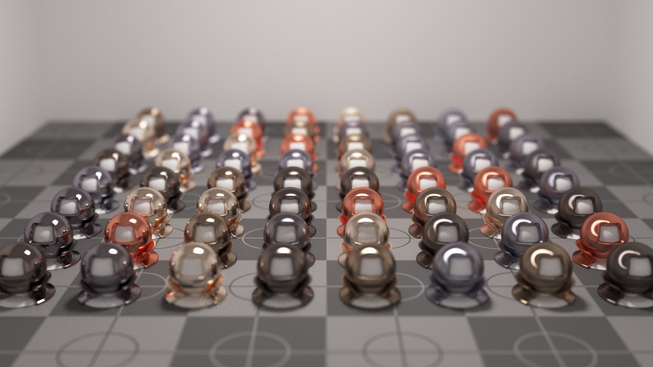
This image was generated using a renderer developed during my PhD using the bidirectional path tracing algorithm.
In ray tracing based rendering algorithms the main performance bottleneck comes from the time it takes to perform intersection tests between rays and the scene geometry. As the number of elements used to represent surfaces within the scene increases so to does the computation complexity of performing these intersection tests.
Rather than testing a given ray against each surface element present in the scene, which would scale poorly with O(n) complexity, acceleration structures such as the KD-Tree and BHV-Tree can be used to reduce the number of intersection tests to roughly O(log n) on average. This is accomplished by traversing a binary-tree like hierarchy performing a comparatively cheap intersection test between a ray and a cutting plane or axis-aligned bounding-box. When the leaf nodes of the tree have been reached only the mesh elements contained within the leaf node need to be tested against the given ray. After an initial intersected element has been found all nodes of the tree which can only contain elements that would have to be further away than the current closest intersection can be ignored as the tree traversal continues, yielding significant performance gains.
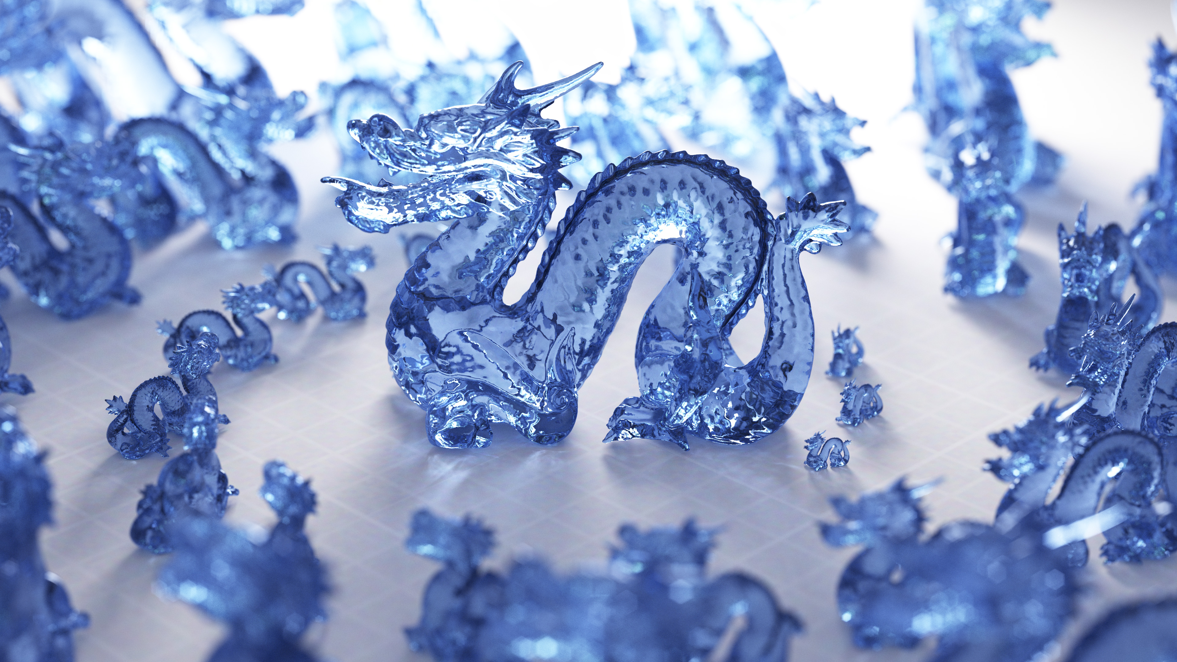
The Stanford Dragon model shown in this image contains 871,414 triangular mesh elements. In the above image, 99 copies of the dragon are present. By a naive scene construction method this would total 86,269,986 triangles. This has the effect of greatly increasing the memory requirements and size of the resulting BVH-Tree. In an ideal world we would only store the dragon mesh and a BVH-Tree over its elements once, and have a system for replaying this data efficiently in arbitrary positions, rotations, and scales.
To this end I have implemented geometric instancing as a feature within the rendering software developed for my PhD research. This is done through a coordinate-space transformation and cross-linking injected into the acceleration structure traversal. The dragon mesh is loaded into the renderer, and a BVH-Tree is constructed for the single dragon model. The root node of the BVH-Tree's bounding box is then duplicated through independent affine-transformations into the size, rotation, and position of each of the desired dragons. Another BVH-Tree is then constructed over the these bounding boxes, along with the triangles making up the floor, walls, and light source of the scene. During traversal of the BVH-Tree, when one of the transformed bounding boxes is queried, the given ray is transformed by the inverse of the affine-transformation matrix for the current bounding box. This inverse transformed ray is then intersected with the BVH-Tree containing only the dragon mesh. The resulting intersection location can be found by scaling the original ray by the resulting distance to the closest intersection found, regardless of whether the intersection was within one of the nested bounding boxes.

With some additional work, each instanced mesh can have different materials applied to it through a stack based shading hierarchy which is also tracked during BVH-Tree traversal.